Cross-Country Soaring 2004
![]() User Guide
User Guide ![]()
9.3 Creating and Using Slope Lift
Flight Simulator (FS) does not automatically create slope lift. Before Cross-Country Soaring (CCS), the only way to simulate slope lift in FS was to painstakingly create and use scenery (BGL) lift. Since Version 3.0, CCS 2004 has provided the ability to generate much more detailed and realistic slope lift over a large area with much less work required of the user.
Before you can experience CCS slope lift in a given area, you (or someone else) must generate one or more special CCS files containing the slope data for the area. CCS uses the data in such files to create slope lift/sink given the wind conditions. If you have the file(s) you need already, just place it(them) in your CCS “Import” folder (*.dat files only) or “Slope Data” folder (*.slo files only). CCS will automatically use the data in the file(s) with no other action on your part. This slope data is now a permanent part of CCS’ slope data “library”, so you’ll never have to create or import this same data again. For more about the CCS slope data library, see The Slope Data Library.
If you don’t have a CCS slope data file for an area in which you want slope lift, then see the steps below for creating one. See Quick Start to experience CCS slope lift using sample slope data included with CCS.
Important Notes about FS Winds
CCS slope lift and sink are based on the wind conditions at your altitude, not at the surface. Therefore, be careful when setting up winds for slope soaring that you set up winds as high as you plan to fly. To do this, you should use the FS “Advanced Weather” page to create aloft wind layers as high as you expect to fly. Press SHIFT-Z in flight to display the wind speed and direction at your current position (including altitude), if you don’t find slope lift/sink where you expected to find it.
1. Determine the latitude and longitude bounds of the desired area. You can get this information from a number of sources, including printed topographical maps and online topographical maps (e.g., Maptech MapServer). Because of the extensive processing required to set the plane’s latitude and longitude while conducting the topography scan, a 100 square mile area at about 40 degrees latitude will take about an hour to process. (Exact processing times will vary based on individual computer performance.) CCS has no limit on how large an area you can scan, but consider the required processing time when deciding the size of the area to process. You cannot use FS, while CCS is scanning the terrain.
2.
 On
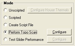
the CCS Control Panel main window, select Perform Topo Scan mode, and click Configure. You’ll see the Topo Scan Settings
window.
On
the CCS Control Panel main window, select Perform Topo Scan mode, and click Configure. You’ll see the Topo Scan Settings
window.
3. Enter the latitudes and longitudes that define the bounds of the rectangular area in which you want to generate slope data (i.e., in which you want to create slope lift/sink). Use the DD.DDDD format, where North and East are positive.
4. Select Save Elevation Data if you want CCS to save (to the CCS program folder) the raw elevation data file (“ccs-elev.dat”) created during a terrain scan. This file is not needed and is normally not saved. This option is included in order to make the raw elevation data available, if desired, to software developers interested in using it.
5.
Enter a Move-Read
Delay if needed. Most users will not
need a move-read delay. However, some
slower computers 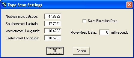 may
generate bad scan data using the default setting (0, which actually means a
fixed value less than one millisecond).
This option is included to make it possible to generate good scan data
on such a computer. If your computer
generates bad scan data with the default setting (0), then try higher delays,
until the scan data is good. See below for instructions on how to determine whether scan data
is good or bad.
may
generate bad scan data using the default setting (0, which actually means a
fixed value less than one millisecond).
This option is included to make it possible to generate good scan data
on such a computer. If your computer
generates bad scan data with the default setting (0), then try higher delays,
until the scan data is good. See below for instructions on how to determine whether scan data
is good or bad.
6. When you’re happy with these topo scan settings, click OK.
7. Start FS, and open any saved flight (preferably, but not required, in the vicinity of the defined area).
8. Make sure FS is in a cockpit view (not tower or spot plane view). Otherwise, the scan may produce bad results.
9. Disable your joystick in FS. This is not required, but is recommended. If the joystick is enabled, and you bump it during the scan, CCS could get erroneous topographical data, resulting in erroneous slope lift/sink behavior.
10. Click Exit and Launch Cross-Country Soaring in the CCS Control Panel main window.
11. Enter a name and location for the slope data file the topo scan will create. If you want CCS to import the data (making the scanned area ready for slope soaring), then save the file in CCS’ Import folder.
12. After your aircraft position has stabilized in FS, click OK. It is recommended that you wait to click OK until your hard drive activity slows to normal, if it is active after starting CCS. Otherwise, CCS may retrieve bad data during the first several seconds of its topography scan, resulting in wrong slope data in the most southerly part of the area being scanned.
13. Do not minimize FS during the scan. This has been known to cause the scan to produce bad results.
14. During the scan, CCS writes the scan progress percentage to the FS screen.
15. When the scan completes, click OK to the “complete” message. CCS will automatically exit.
More about the Terrain Scan
The terrain scan simply collects elevation data at points on a three second (3”) latitude/longitude spaced grid. Thus, CCS collects 1,201 elevation data points for each linear degree (~69 mi. at the equator). This collection of data is used (after the scan) to generate “slope data” on this same grid. Slope data, as defined by CCS, is simply the steepness and directional orientation of the terrain at that point.
Before the scan begins, CCS moves the plane to the southwest corner of the area to be scanned. CCS also moves the plane to an altitude of 20,000’ MSL, in order to keep the plane above any terrain being scanned. When you click “OK” to begin the scan, CCS begins moving the plane about horizontally, collecting elevation data at each point. The plane first moves west to east, three seconds longitude at the time, until it reaches the eastern edge of the scan area. Then the plane moves three seconds to the north and begins moving east to west, three seconds longitude at the time, until it returns to the western edge of the scan area. The plane then moves three seconds to the north and repeats the back-and-forth scan, until the entire area has been scanned.
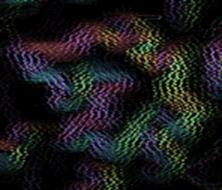
For best results, perform the scan on your fastest computer. CCS does not have perfect control of the scan, so it’s possible that a slower computer might not be able to update the FS scenery (terrain) as quickly as CCS moves the plane from point to point in the scan area. (If you find this to be the case with your computer, use the move-read delay setting to slow the scan speed.) Also, you may find that CCS performs better scans when FS and CCS are the only programs open and when FS scenery complexity is minimal. Scan errors will present themselves as slope lift/sink strength or location problems. The best way to “validate” a scan for correctness is to use a program called “JCSDAT”, written by SOAR member Peter Lürkens. JCSDAT produces a color image of the resulting slope data file. This image should correlate to the scanned terrain. Typically, a bad scan results in “jitters” in this image. Visit Peter’s web site or the SOAR message board to download JCSDAT and get more information on it. Here are two JCSDAT-output images for the same area. Black indicates flat ground, and color indicates slope. Different colors indicate different directional orientations, and steeper slopes are more brightly colored. The image on the left is from a good scan. The image on the right is from a bad scan. If your computer produces an image like the one on the right, then try one or more of the ideas in this paragraph, and repeat the scan.

CCS Slope Data & FS Terrain Data
FS comes with standard, global terrain data. Improved terrain data, however, is available from various sources at some or no cost. The results of a CCS terrain scan will vary, depending on the terrain data installed in FS for the scanned area. Therefore, the best CCS slope soaring results will be seen when using CCS slope data that was generated using the same FS terrain data you have installed for the area. If you have never installed terrain data in FS and only use CCS slope data files you generate yourself, then you will see ideal results. Because of the time it takes to conduct CCS scans, however, users may want to share slope data. If you use data generated by another user, make sure you know what terrain data was used to generate that data. Ideally, you should install the same terrain data on your computer if you plan to use the other user’s slope data. Otherwise, due to slight differences in terrain data, you may not find the slope lift/sink aligned perfectly with your terrain and may find the lift/sink slightly stronger or weaker than you would expect given your terrain. During beta testing of CCS 2004 Ver. 3.0, SOAR members set up an FTP area for sharing CCS slope data. Visit the SOAR message board for more information, or click here to go directly to SOAR’s CCS slope data download area.