![[MWA Engineering Dept.]](Low-pass filters_files/circuitheader.gif)
![[MWA Engineering Dept.]](Low-pass filters_files/circuitheader.gif)
"Station WRNY is equipped with the latest device known to the world of radio engineering, called a harmonic suppressor, the effect of which is the elimination of the signals of WRNY from every frequency except that to which it has been assigned by the Government, which means, in fan language, that the station may be tuned in on only one setting of the dial." —Radio News magazine, August 1925
A low-pass filter attentuates the energy above a specified cut-off frequency. These filters are used to reduce the intensity of harmonics so that they don't interefere with other signals. Most of this filters on this page were designed for various ham radio gear operating in the bands from 1.8 to 14 MHz.
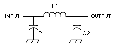
Unless otherwise noted these filters have 50 or 52 ohms input and output impedance. Capacitances are expressed in picofarads, inductances in microhenries. Most authors recommend using silver-mica capacitors.

| for transmit frequencies in the range of | C1 | C2 | L1 |
| 1500-2000 kHz | 1800 | 1800 | 30 turns #26 wire on T-50-2 toroid |
| 3500-4500 kHz | 680 | 680 | 21 turns #22 wire on T-50-2 toroid |
| 5500-7300 kHz | 470 | 470 | 14 turns #22 wire on T-50-2 toroid |
| 5500-7300 kHz | 820 | 820 | 2.2 |

| approx. cutoff freq. | C1 | C2 | C3 | L1, L2 | info source |
| 1200 kHz | .0039 uF | .0056 uF | .0039 uF | 6.8 | North Country Radio AM88 kit design |
| 1800 kHz | .0033 uF | .0043 uF | .0033 uF | 5.6 | North Country Radio AM88 kit design |
| 2000 kHz | 1592 pF | 3184 pF | 1592 pF | 3.98 | Solid State Design for the Radio Amateur |
| 7300 kHz | 470 pF | 1000 pF | 470 pF | 42 turns #26 wire on T-50-2 | Solid State Design for the Radio Amateur |

| cutoff frequency (in MHz) | 30 dB attenuation point (in MHz) | C1, C4 | C2, C3 | L1, L3 | L2 |
| 2.16 | 4.0 | 820 | 2200 | 4.44 | 5.61 |
| 4.12 | 7.3 | 470 | 1200 | 2.43 | 3.01 |
| 7.36 | 12.9 | 270 | 680 | 1.38 | 1.70 |
| 10.37 | 15.8 | 270 | 560 | 1.09 | 1.26 |
|
Based on an article by Ed Wetherhold published in UK Short Wave (Dec. 1983). | |||||
![]()
return to transmitter
building blocks page or Engineering
Dept.
![]()