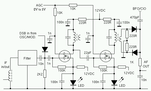
I.F. Amplifier
I.F. AmplifierThe I.F. amplifier is similar to the one used in
the 80M receiver project
. The original design has been modified by putting a couple of LED's in the
source circuit of each Mosfet. The voltage drop across the LED's keeps the
source voltage at about two volts. This results in a much greater AGC range.
This arrangement was suggested by N6BIU. Thanks Jim.
The I.F. transformer
primary has 18 turns, the secondary winding has 4 turns. The capacitors across
the IFT primaries are 82pF. The input/output transformer has 12 turns, tapped at
3 turns from ground. This transformer is wound on a ferrite core. The mosfets
are 3SK45's. The diodes in the product detector are 1N34's. I use a six pole SSB
filter from a scrap CB. The centre frequency is 7.8MHz. The -6db bandwidth is
about 2.5KHz.
Update: 8 Feb. 2002.
Since I built this
rig, I have replaced the original IF amplifier board with a completely new unit.
I used a dual-gate mosfet as the first IF amplifier and a Motorola MC1350P as
the second IF amplifier. The low noise of the mosfet combined with the excellent
AGC characteristics of the MC1350P results in a very good IF amp.
The
schematics for the new IF and AGC modules are below. I haven't had time to make
a careful check for errors, please let me know if you find any.
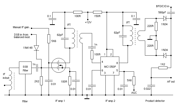
New IF amplifier
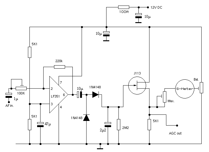
New AGC circuit
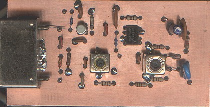
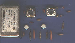
PCB top view
BACK TO HF TRANSCEIVER
PAGE
EI9GQ HOME BREW RADIO
PAGE