NW2M Presents:
The Yaesu FT-101 HF Transceiver Home Page

The FT-101 series of transceivers first appeared outside of the United States in 1970 and then inside the United States in late 1971. It gained overnight approval of amateur radio operators for its quality of signal, flexibility and for professional attention to workmanship and design. The modular design of 10 solid state circuit boards on a common chassis with a tube amplifier caught the eye of discriminating hams world wide.
It was a strong performer. Although far from perfect, the first FT-101's suffered from intermod when strong signals were present during receive and generated spurs on transmit. Hams began to investigate these problems and offer improvements to existing circuit design. The factory responded with a major modification which significantly improved the receiver of the early FT-101's. The serial number revealed which transceiver was "early" and "late". So that the "early" FT-101 hams would not feel obsolete, Yaesu offered the entire modification which made an "early" into a "late" and sold it as a kit along with a 25 page instruction guide. Problems began as many hams lacked the proper test equipment and the know-how needed to make such an upgrade. After months of fighting with customers, Yaesu withdrew the kit (MIR-1 Modification Kit) and would only install it at their factory. Adding to the confusion was the fact that there were five (5) different sub-models within the "early" FT-101 series, the last being the FT-101 "late" model. The situation arose where identical FT-101 radios sat side by side with the only indication of the internal layout was by the serial number.
Additional improvements were made and with the addition of the 160 meter band, the FT-101B was released. Yet more improvements and the addition of a real "RF" speech processor led to the release of the FT-101E model. The "E" model was fully refined with all of the previous problems having been worked out. This was the most popular and the most produced model by Yaesu in the FT-101 series. Three models of the "E" were released. The "E" model with all options, an "EE" (economy) model lacking the speech processor, and the "EX" (extreme economy) model lacking speech processor, 160M crystal, DC options, and microphone. Last in the series was the "F" model which contained all of the modifications, improvements and options throughout the series. Only a few of the "F" models were made which also included an "FE" (economy) and "FX" (extreme economy) model. With fierce competition in the HF market, WARC bands on the horizon, IF shift, AF Notch/Peak, and digital readouts, the FT-101 series moved quickly to the analog "Z" model and then to the digital "ZD" models. The original FT-101 series lasted for 8 years, beginning in late 1971 and lasting through 1979. It was an exciting time for the FT-101 radios and their owners.
There were no "A", "C", or "D" models produced.
A publication called the Fox-Tango Newsletter captured the "diary" of the FT-101's for all time. Ten publications per year offered thousands of FT-101 owners the opportunity to share problems, solutions, and performance data. The Fox-Tango Newsletters lasted for 14 years. It is the largest collection of user data and factory support information for any radio at any time. It has been preserved and full copies are still available today. Truly a testament to the era and popularity of these radios, even today.
|
|
VFO | REG | HF/IF | LO/IF | AUDIO | RF | MOD | RECT | BLANKER | PROCESS |
| FT-101 (Early) S/N 25,000&Down |
|
|
|
|
|
|
|
|
|
|
| FT-101 (Late) S/N 25,001&Up |
|
|
|
|
|
|
|
|
|
|
| FT-101B (Early) S/N 6,000&Down |
|
|
|
|
|
|
|
|
|
|
| FT-101B (Late) S/N 6,000&Up |
|
|
|
|
|
|
|
|
|
|
| FT-101E/EE/EX (Early) S/N 15,000&Down |
|
|
|
|
|
|
|
|
|
|
| FT-101E/EE/EX (Mid) S/N 15,000-20,000 |
|
|
|
|
|
|
|
|
|
|
| FT-101E/EE/EX (Late) S/N 20,001&Up |
|
|
|
|
|
|
|
|
|
|
| FT-101F/FE/FX (All) S/N All Numbers |
|
|
|
|
|
|
|
|
|
|
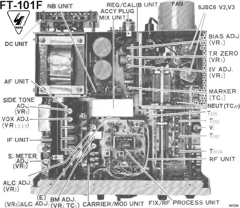
The tube amplifier consists of a 12BY7A pre-driver stage that feeds a pair of 6JS6C tubes providing a nominal output power of 130 watts PEP SSB, 90 watts CW, 40 watts AM. The 6JS6C tubes are matched to 50 Ohms through a conventional pi-output network. The pi-network transforms the 3000 ohm output impedance of the tubes to a 50 Ohm feed system, provides harmonic attenuation, and can actually match to a variety of output impedances from 25 to 100 Ohms with ease.
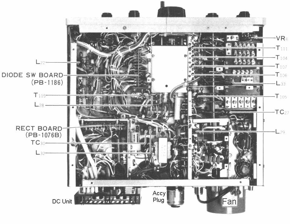
The transceivers were made with plug-in boards that could be sent to the factory for replacement or repair. This modular design was unprecedented in the amateur community, which explains why so many FT-101's are still in use today. In fact, board extenders could be purchased to extend any board above the main chassis for measurement, alignment, and repair. For any plug-in board, all voltages, grounds, and signal traces were routed through a single edge connector (facing down into the main chassis). This removed the need for wires and cables to these circuit boards. This yielded a clean and trim internal upper chassis. The bulk of the wiring harness is below the deck of the main chassis where all main circuit board edge connectors are fed. Yes, there are many wires!
FT-101 Bottom Chassis Photo 91k
Please print landscape, margins set to 0.25", 300 or 600 DPI gray scale
The most complicated device in this radio is the Band Selector Switch. This is a 12-position rotary switch that runs from the front of the radio to the back. It has 13 sections (wafers A thru M) which route everything from DC voltages, oscillator sections, crystals, tuning circuits, and RF Power in the high-voltage tank and output circuits. One band selector switch position is used for: 160M, 80M, 40M, 20M, 15M, 10A, 10B, 10C, 10D, 11M or AUX, and WWV receive-only. Each position allows the main VFO to cover 500kHz on any band.
The entire transceiver was made of metal. Covers, chassis, shields, shafts, etc., are all metal. Even the plastic RF/S-meter trim and knobs have brass metal inserts. At 35 pounds, there is a lot of metal in this radio! The 10 major circuit boards are mounted with threaded hardware to the main chassis. Very rugged indeed. A clear plastic sheet covers the entire painted surface of the faceplate. A well-cared-for FT-101 will still have this clear plastic front.
Because critical circuit designs were kept to a manageable size, hams had no problem in offering circuit changes, isolating and repairing problems. This knowledge base was so active that in January 1972, Milton Lowens WA2AOQ, founded the International Fox Tango Club and the Fox Tango Newsletter. The Fox Tango Newsletters were published for 14 years covering the early FT-101's thru the latest Yaesu Transceivers in 1985. By then, surface mount technology and circuit complexity outpaced many ham's ability to maintain this level of equipment. In doing so, new chapters in circuit densities, solid state transmitters, and LSI chips were born, which closed the door (and the covers) to many radios.
Frequency Range:  3.5-30 MHz*   (80/40/20/15/10 meters)
                  27.0-27.5 MHz (11/AUX)
                  10.0-10.5 MHz (WWV receive only)
                  * 160 meters included with B/E/F Series
Modes:            USB, LSB, CW, AM
Power Input:      SSB 260 watts PEP DC Input (130 watts output)
                  CW 180 watts PEP DC Input  ( 90 watts output)
                  AM 80 watts PEP DC Input   ( 40 watts output)
TX Freq Response: 300 Hz - 2700 Hz
RX Freq Response: 300 Hz - 2400 Hz Standard Yaesu SSB Filter
                  500 Hz           Optional Yaesu CW Filter
Optional Filters: 300 Hz - 1800 Hz SSB Narrow(Fox Tango Filter)
                  250 Hz           CW Narrow (Fox Tango Filter)
Audio Output:     3 watts
AC Power:         Rx 35 watts, Tx 300 watts
DC Power:         Rx 0.5 amps, Tx 20.0 amps
Weight:           35 lbs
Size:             13-1/2" x 6" x 11-1/2"
FV-101B External VFO
Adding the FV-101B
External VFO to your station opens up a new world of operating flexibility.
DX'ers will really appreciate this combination. The FV-101B features the
same factory sealed, solid state, 1kHz resolution, VFO that is found inside
the FT-101 transceiver. This flexibility allows for "split" operation for
separate transmit and receive frequencies in any band. Regardless of VFO
mode, the exact transmit and receive frequency are available for the Digital
Display (YC-601 or DD-1) unit. Please note that any frequency split occurs
within the same band. The Remote VFO does not offer cross-band operation.
Four VFO modes are supported:
YO-100 / YO-101 Monitor Scope
| YO-100 Schematic A | YO-100 Schematic B |
Adding the YO-100 Monitor Scope allows you to monitor and adjust your
transmitter for the cleanest signal possible. Compatible with virtually any
transmitter or transceiver, the Station Monitor features a wide range of
inputs for all mode monitoring, even RTTY. A built-in 1500 Hz and 1900 Hz
tone generators adds to the versatility of this accessory. The two-tone
generator generates the proper audio signals to perform "trapezoidal"
pattern testing for transmitter linearity. A full compliment of front
controls allows operator control of all key adjustments. The YO-101 is a
solid state version of the YO-100.
YO-100 / YO-101 Monitor Scope Specifications:
A 24 hour station clock is a must-have accessory for any operator. The current name and format for world time is called Universal Time Coordinate (UTC). It has also been known over the past years as Greenwich Mean Time (GMT), and the military term ZULU (Z). All world time is represented in a 24-hour format based upon the global starting point in Greenwich, England (UK). The UTC time standard does not adjust for Daylight Savings Time in the United States.
Accurate time reception can be found by tuning to WWV (10.000MHz) on the FT-101 transceiver. Alternate frequencies for WWV and WWVH are 2.500, 5.000, 10.000, 15.000, and 20.000 MHz. All time formats are AM broadcasts. CHU in Ottawa, Ontario (Canada) can be found in the 40 meter band 7.335 MHz, 3.330 MHz, and 14.670 MHz. The WWV (male voice) originates from Ft. Collins, Colorado (USA). The WWVH (female voice) originates from Kauai, Hawaii (USA). The ultra-high accuracy of the WWV 10.000MHz signal is also used to calibrate (zero-beat) the FT-101 internal marker located on the Regulator Board (TC1).
The SP-101PB contains all of the excellent audio properties and characteristics as the SP-101 speaker-only model with the addition of a hybrid telephone-patch circuit. This circuit allows the FT-101 transceiver to be interconnected to your telephone circuit to allow telephone calls to be placed with over-the-air stations. The SP-101PB has two level controls to ensure proper audio levels are presented to the telephone lines. A built-in VU-meter is used monitor the phone-input levels. Connection to the telephone line is via (two-wire) twisted pair (normally red and green wires).
NOTE: When using the phone patch, you are engaging in third-party traffic in which you are the control operator. The US does not have 100% third-party traffic agreements with all countries. Example: I was unable to make a phone patch for a ham on a small sailboat on vacation in the Bahamas/C6 to their parents living 3 miles from my house! The US does not have third-party traffic agreements with the Bahamas. Beware!
                     Item               Price Price Price Price Price Price Price Price Price Price
 Model            Description           Q3/71 Q3/72 Q3/73 Q3/74 Q3/75 Q3/76 Q3/77 Q3/78 Q3/79 Q3/80
---------|-----------------------------|-----|-----|-----|-----|-----|-----|-----|-----|-----|-----|
FRdx400    80M-10M All Tube Receiver     $359              $339
FRdx400SD  80M-10M+6M+2M All Tube Receiver                 $399
FLdx400    80M-10M All Tube Transmitter  $299
FRdx401    80M-10M All Tube Receiver
FLdx401    80M-10M All Tube Transmitter
FTdx401B   80M-10M All Tube Transceiver                    $599
FTdx560    80M-10M All Tube Transceiver  $450
FTdx570    80M-10M All Tube Transceiver        $550
FL2000     80M-10M Linear for dx Series  $299              $339
FT-101     80M-10M Transceiver           $499  $560
FT-101B   160M-10M Transceiver
FT-101E   160M-10M Transceiver                             $649              $729  $799  $695*
FT-101EE  160M-10M Transceiver                                               $649  $759
FT-101EX  160M-10M Transceiver                                               $589  $699
FT-101ES  160M-10M Transceiver(50 watt version for Japan market)
FT-101F   160M-10M Transceiver                                                     $799
FT-101FE  160M-10M Transceiver                                                     $759
FT-101FX  160M-10M Transceiver                                                     $699
FT-101Z   160M-10M Transceiver                                                     $749        $599*
FT-101ZD  160M-10M Digital Transceiver                                                   $895  $749
FT-101ZD  160M-10M Digital Transceiver (WARC)                                                  $799
FT-901D   160M-10M Digital Transceiver (WARC)                                     $1299
FT-901DE  160M-10M Digital Transceiver (WARC)                                     $1149
FT-901DM  160M-10M Digital Transceiver (WARC)                                     $1299 $1459
FL-2100B  Linear Amplifier 80M-10M                         $339              $399  $479
FL-2100F  Linear Amplifier 80M-10M                                                       $399*
FL-2100Z  Linear Amplifier 160M-10M                                                $399*
FV-101B   Remote VFO                                        $99              $109  $135  $116
SP-101    Speaker-Only                                      $19               $22   $25         $22*
SP-101PB  Speaker with Telephone Patch                      $59               $59   $67   $57
FTV-650   6 Meter Transverter                              $149              $199  $235
FTV-250   2 Meter Transverter                                                $199  $275        $225*
YC-601    Digital Display (Yaesu)                                            $169  $199  $205
YO-100    Station Monitor Scope (Tube Model)                                 $199  $233  $240
YO-101    Station Monitor Scope (Solid State)                                      $320        $199*
FR-101    Analog Receiver 160M-2M                                            $489
FR-101    Digital Receiver 160M-2M                                           $599  $599  $549
FR-101S   Analog Receiver 160M-2M                                                  $599  $449  $349*
FR-101SD  Digital Receiver 160M-2M                                                 $749
FL-101    160M-10M Transmitter                                               $525  $575  $499  $399*
YP-150    Dummy Load - Watt Meter                                                   $86   $78   $79*
RFP-101   Speech Processor                                                    $79   $79
YD-844    Base Station Microphone                           $29               $29   $29
YD-846    Hand Microphone                                                     $16   $16
QTR-24    World Clock                                                         $30   $35         $29*
FA-9      Fan                                               $19               $15   $20
MMB-1     Mobile Mount for FT Series                        $19               $19   $23
XF-30C    CW Filter 500 Hz                                  $45               $40   $40
XF-30B    AM Filter 6kHz                                                            $40
DC-1      DC Converter for EX Models                                          $45   $50
Crystals  Any FT-101 Crystal 160M-10M                        $5                $5    $5
DD-1      Digital Display (Spectronics Model)              $169              $169

* - Indicates Advertisers offering "close-out" prices to reduce stock.
There will come a time when the finals in your FT101E will need replacing. The FT-101 transceivers were originally equipped with 6JS6C tubes manufactured by NEC and Toshiba. Other manufacturers tube properties are slightly different from the original 6JS6C tubes. Therefore, a simple modification to the neutralization circuit must be made to the final section of the transceiver. The modification consists of replacing the fixed value 100 pf 1000 VDC mica capacitor with a 10 pf 1000 VDC mica capacitor. This capacitor, C125, is in series with the 10 pf variable neutralizing capacitor off of the plate circuit.
If this modification has not already been completed on your rig, be sure to use a mica or silver mica of at least 1000 VDC. Do not substitute a different type because the heat in the final compartment will change the value, and your tubes will fail prematurely. Also, be very careful to keep all leads short and in exactly the same orientation as the original capacitor.
Before re-neutralizing, open the variable neutralizing capacitor all the way to minimum engagement and follow the neutralizing instructions in the manual. While dipping the PLATE, remember to adjust the neutralizing capacitor for equal value meter reading "dips" (Ic meter position) on both sides of the peak when tuning the PLATE control. WARNING! You are tuning a capacitor in the High Voltage compartment, +600 Volts are present! Always use non-metallic tuning tools. After neutralization, reset the bias to 60ma with CARRIER and MIC settings at minimum.
Or, Search the web yourself -> 6JS6C
QST- The following performance data is provided by the American Radio Relay League (ARRL) and their publication QST. A full copy of this table was found on the Technical Information Service section on the ARRL web page. The table depicted over 60 radios and their performance data. I have shown only the Yaesu radios from the 1970's that apply to this web page.
                       QST Reviews of Amateur HF Transceivers
             QST   |         Xmtr         |          Rcvr
     Rig     Review| Harm.   Spurs   IMD  |  Min Sig BlkRng  IMD DR  3rdO Icpt
             Issue | dBpep   dBpep   dBpep|  dBm     dB      dB      dBm
     -------------------------------------------------------------------------
     Yaesu:
     FT-101B 02/74
     FT-101E 09/76                   -34     -141    108     81
     FT-101Z 12/79   -45             -38     -139    112     78      -22
     FT-301  10/77   -55     -68     -40     -133    100     75
     FT-901  11/78   -46     -57     -38     -137    114     85
If you have ever purchased a FT-101 transceiver without the Instruction Manual, you know it can be very intimidating to operate until you perform the tune-up process a time or two. Without 'tuning up' your transmitted and received signals really suffer AND could actually damage the tubes in the power amplifier. I always suggest that you obtain the Instruction Manual for any FT-101 radio or accessory you own. Even older radios have web pages that can provide you copies at very reasonable rates. An Instruction Manual was made for each and every FT-101 radio and accessory. They are worth every penny. No excuses!
The FT-101 series is a very mechanical radio. The size, selection, and operation of this rig allow for very high-Q circuit tuning. It is a very strong point with the FT-101 series. As with any high-Q circuit, it must be continuously tuned for maximum efficiency. Once learned, it takes only a few seconds to perform. You should re-tune anytime you change bands, change antennas, or move a significant distance (in frequency) from where you last tuned up. This may be as large as 200 kHz on the 10 meter band (10-15 turns of the VFO dial) or as little as 15 kHz on the 160 meter band (one turn of the VFO dial).
Before you begin, you should allow the rig to warm up (with the heaters on) for at least 15 minutes. This allows the rig to become frequency and temperature stable. Put the Meter switch into the 'IC' position with the CARRIER and MIC control fully counter-clockwise. Throw the MOX switch to engage the transmitter and read the meter that is now displaying the idling current. The current should read 60ma on the scale. If it does not, adjust the BIAS control until 60ma is obtained. Move the Meter switch to ALC and ensure a full meter deflection to the right. Adjust the ALC control as needed. Return the MOX switch to normal PTT.
Please remember to tune-up into a well-matched antenna system or dummy load representing a 50 Ohm load. Keep all tune-up steps to under 10 seconds of transmitting to prevent damage to the Power Amplifier tubes! After each 10 second transmission, allow the tubes to cool for a few seconds. Then repeat.
The earlier FT-101 manuals used a tune-up procedure which 'peaked' the output (PO) while 'dipping' the grid (Ic) current. By the FT-101F series, the procedure was simply a 'peaking' (PO) process as depicted in the Instruction Manual. With a little practice, you will be able to perform these procedures within 10 seconds. Really!
Adjust CARRIER, MIC, and PROCESS controls for the proper output as desired. Monitor the Meter for grid current (Ic) and ALC levels (ALC) to ensure that you are not over-driving the transmitter. Both will greatly shorten tube life, cause distorted transmitted audio, and is the prime source of television interference (TVI).
One of the most misunderstood and mistuned modes available on the FT-101 transceivers is the AM (Amplitude Modulation) transmitter. (Second only to the RF Speech Processor!) The FT-101 has one of the best on-air signals for AM that you may ever find in a stock radio. It is also one of the easiest to make a mistake. The most common mistake is measuring AM power the same way that you measure SSB or CW signals using a watt meter. AM is very different.
The most common mistake is running too much carrier power in AM mode. The FT-101 can only deliver 30-40 watts of AM carrier in linear service. The reason for this is that an AM signal contains a steady carrier and two sidebands that contain your audio. The amount of RF power in this modulated AM "envelope" is actually 4-times the carrier. This means that a modulated AM signal with a 30-watt carrier is actually transmitting 120 watts of power. This is the amount of power needed from the power supply to transmit this signal. It is also approaching its absolute power limit. The same is true with the matching FL-2100B amplifier. A 300-watt carrier contains 1200 watts of RF power when fully modulated. There is nothing worse than "cooking" a FT-101 by running AM with a 100 watt carrier. The power supply, tubes, and amplifier components cannot deliver 400 watts of power, are run continuously beyond their maximum rating, and for long periods of time. Beware when purchasing one of these 11 meter 'cooked' radios!
FT-101 Modifications
More info to follow.....
Alignment Points and Procedures
More info to
follow.....
Buy / Swap / Sell Suggestions and
References
More info to follow.....
Sizes and Weights: The sizes and weights for each piece of Yaesu equipment is listed above. None of the Yaesu transceivers or accessories exceed the size and weight limits imposed by any of the major common carriers, such as UPS. Shipping should be a very straightforward process, and with a little planning, your package should arrive in the same condition as it was shipped.
Estimating Final Weight: Accept the fact that shipping will add 20%-25% to the actual weight of any unit. Yes, a 30 pound FT-101E transceiver with manual and power cords will actually weigh 38 pounds ready to ship. A two pound YD-844 microphone will weigh 3-4 pounds if packed properly. The heaviest in the series, the FL-2100 amplifier (41 lb.) will tip the scales at 52 pounds at the counter! Don't underestimate the weight of shipping!
Packing Considerations: Remember that you are responsible for ensuring that the equipment is packed properly and safely for its journey. The longer the trip the better it must be packed, especially overseas. NEVER use newspaper for any of packing material. It is not resilient to compression, it holds moisture, and will leave ink on painted and plastic surfaces. When possible, use the original Yaesu packing box and materials. Prior to shipping any unit, remove all AC cords, microphones, accessory plugs, and the brass spinner on the main VFO dial. Do not use tape on any plastic or painted surface. Ensure that all covers are on tight. Put the unit in a plastic bag (as a moisture and dust barrier), and then wrap in bubble wrap. Select a box which allows at least 2" on each side to survive a hard "knock" while in transit. Place enough fill to cover 2" in the bottom of the box. Insert the unit and fill completely with packing to the top.

Since FT-101 parts are sometimes very hard to find, please ask ANY repair facility how they obtain parts. If the simply call the Yaesu factory, you may be sending your FT-101 to the wrong place or waiting a very long time. I prefer to deal with repair facilities that specializes in FT-101 parts, which means in some cases, they must use 'parts rigs' to find that hard to get part. Basic capacitors, resistors, and transistors are not a problem. But, there are times where a substitute is not available. You will be glad that your rig is being repaired by a "FT-101 ready" facility.
Credits and Source References
More info to
follow.....
FT-101 Transceiver
More info to follow.....
| FT-101 AC Power
Transformer Connection Diagram | AC and DC Power Connection and
Pin-out Diagram |
YC-601 Digital Display
More info to follow.....
2 Meter Transverter
More info to follow.....
6 Meter Transverter
More info to follow.....
| FTV-650 Hook-up diagram |
FTV-650 Schematic A | FTV-650 Schematic B |
73, for now.
Al Rabassa, NW2M
Please visit our club's home page http://www.marcclub.org/
Montgomery Amateur Radio Club, Maryland
Or send email to: mailto:NW2M@QSL.NET?Subject=FT-101-Webpage
Since 1/1/98
Last Update: 09/26/2000 AOR